
English
4mm Tempered Float Glass Sheets for Appliance Door & Panel Systems
6mm Toughened Glass Systems for Refrigerator, Oven & Stove Applications
Tempered Decorative Glass Panel Systems for Refrigerators, Ovens & Range Hoods
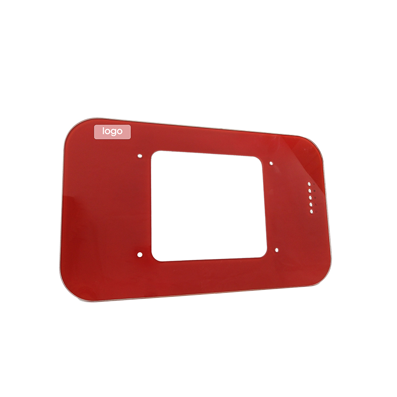
Tempered Glass Panels for Range Hoods – Curved & Flat Designs for Ventilation Systems
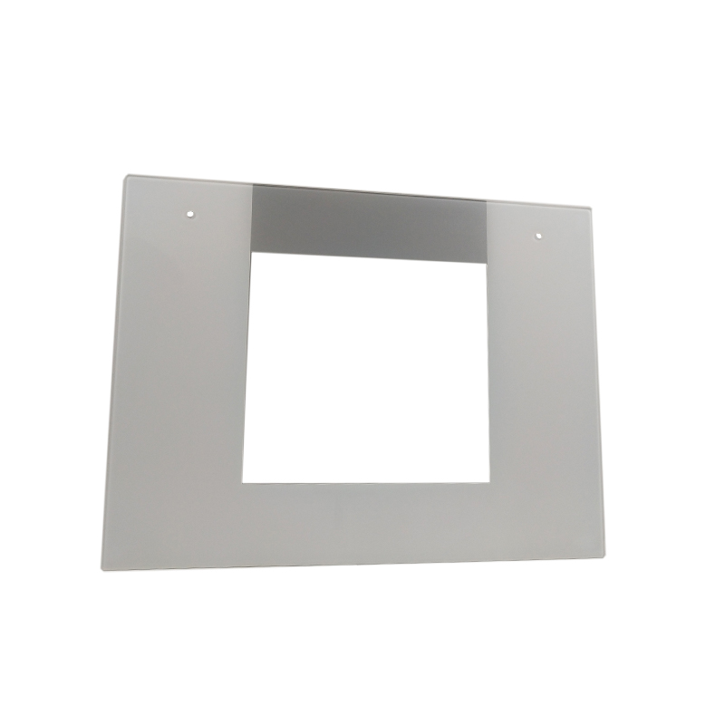
OEM Tempered Glass Control Panels for Kitchen Chimney Hoods – Custom Shapes & Finishes
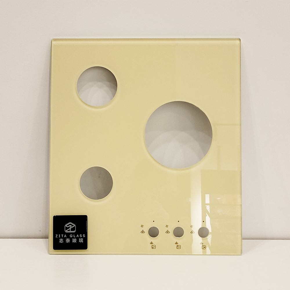
Custom 3 Burner Gas Hob Glass Panels ,Black & Champagne Custom Color Gold OEM Cooktop Glass
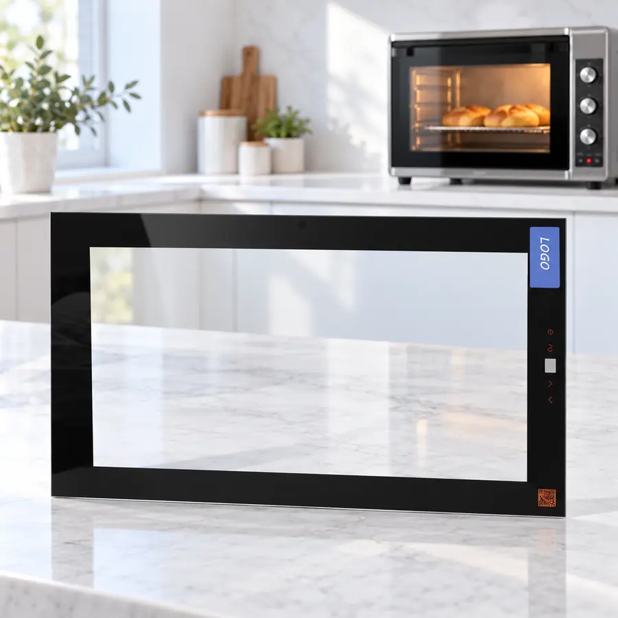
Custom Microwave Oven Door Glass for OEM Appliances,Heat Resistance,Clear
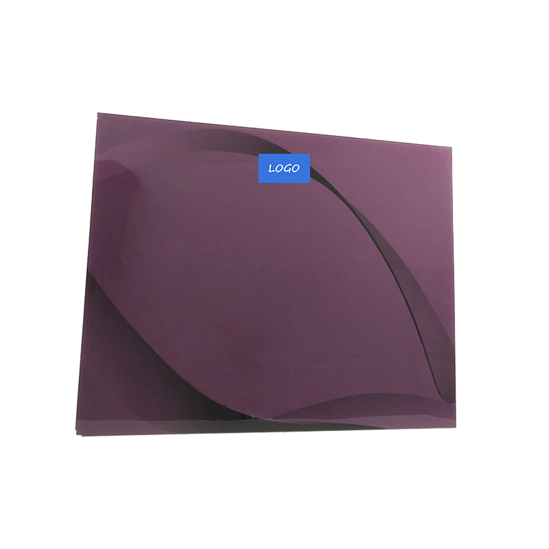
Tempered Glass Door Systems for Refrigeration Appliances – Custom Silk-Screen, Mirror & Frosted Finishes
Custom Glass Drilling for OEM Appliance Panels: Round Holes, Countersinks and Shaped Cutouts
NOV.14,2026ZITA Glass’s Fully Automatic Packaging Line for OEM Appliance Glass
NOV.11,2026OEM Appliance Glass Processing: From Precision Drilling to Quality Control
NOV.07,2026Home Appliance Glass Manufacturing Industry in 2026: Market Trends, Leading Chinese Suppliers & OEM Sourcing Guide
NOV.06,2026Clear Float 6MM Toughened Glass: An Overview
APR.18,2023Oven Door Glass: What You Need To Know
MAR.14,2023Benefits of Choosing a Reputable Tempered Glass Manufacturer
MAR.09,2023Refrigerator part: tempered glass panels
OCT.25,2022Tempered glass panel: what you need to know
OCT.25,2022Importance of tempered glass sheet
OCT.08,2022


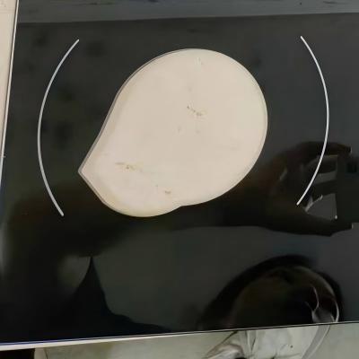
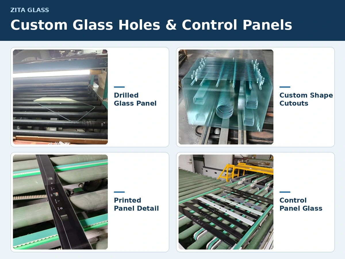
A hole in an appliance glass panel is part of the assembly. Its diameter determines whether a component can pass through. Its position determines whether that component lines up with the frame. Its cross-section can determine how the component seats against the glass. ZITA Glass manufactures custom glass panels with standard round holes, conical openings and non-circular cutouts to match OEM equipment and hardware drawings.
Our precision drilling service covers glass thicknesses from 3 to 8 mm. For suitable designs, hole location can be controlled to ±0.2 mm, subject to drawing review. Hole diameter, cutout profile, recess depth and other critical dimensions are specified separately. We can combine drilling with edge finishing, tempering and screen printing as required by the project.
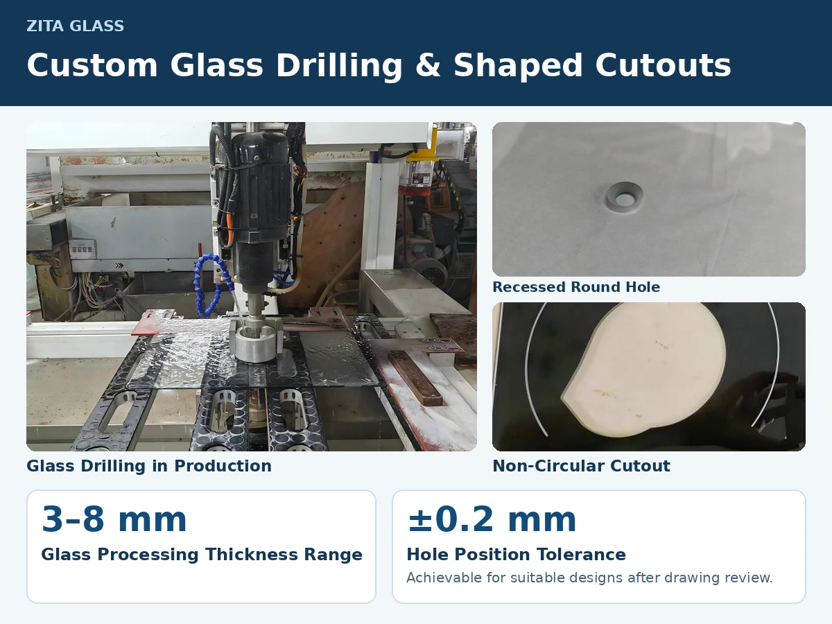
A straight round hole is used for hardware, shafts or other components that pass through the panel. Specify the finished diameter, hole center coordinates and location tolerance from the drawing datums. When several holes align with the same bracket, include the mating part drawing so the spacing can be checked as a group.
A conical recess provides a shaped seat for a compatible component. Its geometry is defined by the through-hole diameter, the opening diameter at the glass surface and the included angle or recess depth. The drawing should also identify which face receives the recess. A section view helps the manufacturer verify how the mating part sits and how much glass remains beneath the recess.
An irregular glass cutout can follow the outline of a burner assembly, control module or other component with a non-circular footprint. Specify the full contour, internal corner radii and its relationship to nearby holes, panel edges and printed graphics. A dimensioned drawing together with CAD geometry gives production and inspection teams a common reference.
A shaped opening can also have a custom cross-section through the thickness of the glass. If the component seats against a curved ring around a round hole, include a section or a 3D model to define that seating surface. The top view describes the outline, while the section describes how the parts fit together.
A European customer needed a glass opening that would mate with a component in a specialized equipment assembly. The requirement concerned the surface around the opening as well as the hole itself. ZITA Glass developed a machining process to form a curved annular seat, with a toroidal profile that matched the mating component.
The curved seat addressed the customer’s assembly fit requirement. For similar projects, providing the mating component geometry and identifying where it should contact the glass helps the engineering team evaluate the opening and seating surface together.
For a thermally tempered panel, drill the holes and machine the cutouts before tempering. If the hole pattern changes, make a new panel using the revised drawing.
The ±0.2 mm figure refers to hole location on suitable designs and is confirmed during drawing review. Agree separately on limits for diameter, profile, recess depth and any dimensions that control assembly.
Yes, subject to drawing review. Send the machining drawing and artwork with shared reference points so the locations of the openings and printed features can be checked together.
Developing a glass panel for a cooktop, appliance control panel, display cabinet or other OEM assembly? Send ZITA Glass your drawing, glass thickness and mating component details. We can review the hole geometry, critical tolerances and sample requirements before you place a production order.